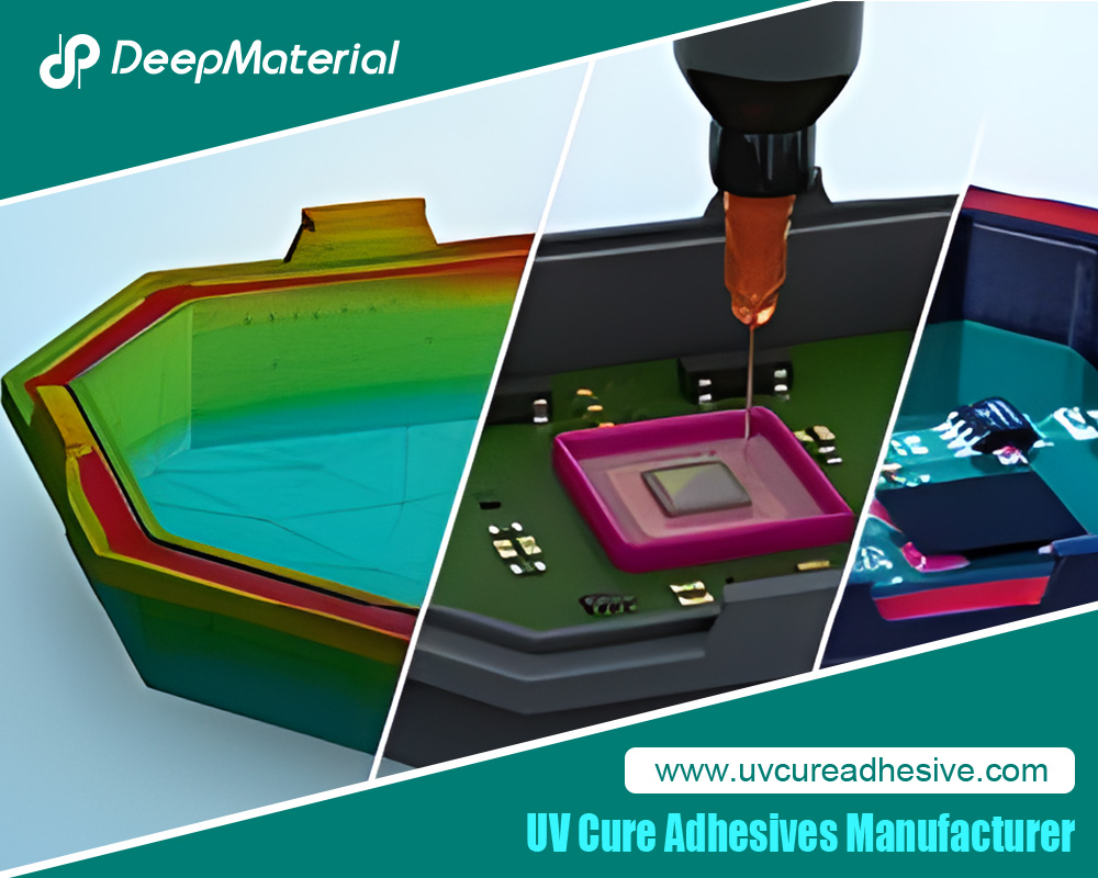
How to Fix Insufficient Bonding Strength of UV Cure Epoxy Adhesive
UV cure epoxy adhesives promise instant, strong, and clean bonds in applications ranging from microelectronics and medical devices to automotive sensors and aerospace composites. Marketed with lap shear strengths of 15–35 MPa on metals and glass transition temperatures (Tg) exceeding 120°C, these single-component systems eliminate mixing errors and enable tack-free assembly in seconds. Yet, field failures—delamination under thermal cycling, peel-off during vibration, or catastrophic rupture in drop tests—reveal a persistent gap between datasheet values and real-world performance.
Insufficient bonding strength is rarely a single-point failure. It emerges from incomplete curing, poor interfacial adhesion, cohesive weakness, or environmental degradation. This 2000-word guide, cause-and-effect guide dissects the root mechanisms, validates them with failure analysis data, and delivers step-by-step corrective protocols. Whether you manage a high-volume SMT line or prototype optical assemblies, the following framework transforms weak bonds into reliable joints.

Understanding Bond Strength Metrics
Bond strength is quantified by:
- Lap shear (ASTM D1002): Peak stress before failure (MPa).
- T-peel (ASTM D1876): Energy to propagate crack (N/mm).
- Cleavage (ASTM D3433): Resistance to wedge opening.
- Push-out or die shear (MIL-STD-883): Critical for IC packaging.
A “strong” UV cure epoxy adhesives>70% of cohesive failure (substrate fracture or adhesive tearing) versus adhesive failure (clean release at interface). FTIR, DSC, and SEM/EDS are essential diagnostics:
- FTIR: Epoxy peak at 910 cm⁻¹<5% of initial intensity = full cure.
- DSC: Residual exotherm <10 J/g = complete polymerization.
- SEM: Interfacial voids or contaminant layers signal adhesion loss.
Root Cause 1: Incomplete Cure
Mechanism
Under-cured epoxy exhibits low crosslink density, reducing Tg and modulus. A 10% drop in conversion can halve shear strength (Figure 1, ref. Dymax study).
Diagnosis
- Tacky surface 60 s post-UV.
- DSC residual exotherm >20 J/g.
- Lap shear <50% of datasheet.
Fixes
- Increase UV Dose
Measure irradiance at bondline with radiometer (e.g., EIT PowerMAP). Target 2000–5000 mJ/cm² for filled systems. Example: A 365 nm LED at 500 mW/cm² requires 4–10 s exposure. - Optimize Wavelength
Match lamp peak to photoinitiator absorption (e.g., 365 nm for Irgacure 250, 395 nm for SpeedCure 73). Use dual-LED arrays (365+405 nm) for thick or pigmented adhesives. - Enable Dark Cure
Select cationic epoxies with latent thermal initiators. Post-UV bake at 80°C × 5 min drives bulk cure in shadowed 2 mm joints. - Verify Cure Depth
Section bond; stain with iodine vapor. Dark brown = cured; pale = uncured.
Root Cause 2: Poor Surface Wetting and Contamination
Mechanism
Contact angle >30° prevents intimate contact. Silicone, oils, or flux residues create 1–5 nm weak boundary layers.Diagnosis
- Water break test fails (beading).
- XPS detects Si 2p or F 1s peaks on failed interface.
- Peel strength <2 N/mm.
Fixes
- Solvent Wipe Protocol
Isopropyl alcohol (IPA) + lint-free wipe, 2× in same direction. Dry 60 s at 60°C. - Plasma Activation
Oxygen or argon plasma (300 W, 60 s) raises surface energy to 70 mN/m. Bonds assembled within 30 min retain 95% strength. - UV-Ozone Cleaning
185+254 nm lamp for 5 min removes hydrocarbons. Ideal for polymers like PEEK. - Primer Application
Silane-based primers (e.g., Momentive A-174) for glass/ceramics; acrylic acid grafts for polyolefins. Apply 1–2 μm film, flash 60 s at 80°C.
(Word count: 678)
Root Cause 3: Substrate-Adhesive
Mismatch
Mechanism
CTE (coefficient of thermal expansion) mismatch induces residual stress. Epoxy CTE ~60 ppm/°C vs. aluminum 23 ppm/°C = 300 microstrain at ΔT = 100°C, fracturing brittle bonds.
Diagnosis
- Thermal cycling (-40/125°C, 1000×) causes 80% strength loss.
- FEA shows stress >yield strength at corners.
Fixes
- Flexible Epoxies
Select formulations with rubber tougheners (CTBN or polyurethane segments). Elongation >10% absorbs strain. Example: Loctite AA 3526 (shear 22 MPa, peel 6 N/mm). - CTE-Matched Fillers
Add 30–50 wt% fused silica (CTE 0.5 ppm/°C). Reduces composite CTE to 25–35 ppm/°C. - Compliant Interlayers
Bond metal to PCB via 100 μm silicone gasket before epoxy potting. - Geometry Optimization
Fillet joints (45° adhesive bead) reduce stress concentration 60% vs. butt joints.
Root Cause 4: Moisture and Environmental Attack
Mechanism
Hydrolysis of siloxane or ester linkages in humid environments (85°C/85% RH) drops strength 50% in 500 h.
Diagnosis
- HAST (130°C/85% RH/168 h) failure.
- FTIR shows new OH peak at 3400 cm⁻¹.
Fixes
- Hermetic Sealing
Conformal coat with parylene-C (10 μm) or dispense dam-and-fill UV epoxy. - Hydrophobic Formulations
Use fluorinated epoxies (e.g., 3M SC-300) with contact angle >100°. - Desiccant Integration
Embed molecular sieves in potting compound for enclosed modules.
Root Cause 5: Over-Curing and Embrittlement
Mechanism
Excess UV dose (>10× required) causes chain scission or micro-cracking, reducing impact strength.
Diagnosis
- Yellowing or haze post-cure.
- Charpy impact <2 kJ/m².
Fixes
- Dose Mapping
Use UV dosimeter strips to confirm <20% overdose. - Controlled Cooling
Ramp from cure temperature at 2°C/min to prevent thermal shock.
Process Optimization Framework
Step 1: Design of Experiments (DOE)
Run fractional factorial with variables:
- UV dose (1000, 3000, 5000 mJ/cm²)
- Surface treatment (none, plasma, primer)
- Adhesive thickness (50, 200, 500 μm)
Analyze via ANOVA; optimize for >20 MPa shear with cohesive failure.
Step 2: In-Line Monitoring
- Irradiance Sensors: Omega UVX-300 (feedback to PLC).
- Cure Confirmation: Embedded fluorescent tracers (shift emission when cured).
- Bond Strength QC: Automated pull-tester on 5% production samples.
Material Selection Guide
| Application | Recommended Adhesive | Key Features | Shear Strength |
| PCB to Al heat sink | Dymax 9-911-REV | Thermally conductive (1.5 W/m·K), flexible | 25 MPa |
| Glass lens bonding | Panacol Vitralit 6127 | Optical clarity, low shrinkage | 30 MPa |
| Plastic enclosures | Henkel Loctite 3211 | High peel, humidity resistant | 18 MPa |
| Medical catheter | Epotek OG116-31 | USP Class VI, low Tg | 22 MPa |
Case Study 1: Automotive Camera Module
Problem: ADAS camera lens detached after 500 thermal cycles (-40/85°C). Shear strength dropped from 28 MPa to 6 MPa.
Analysis:
- SEM: Clean adhesive failure at glass surface.
- XPS: 2.1 at% fluorine from mold release.
- Cure: 1200 mJ/cm² (insufficient for 200 μm black-filled epoxy).
Solution:
- CO₂snow cleaning removed release agent.
- Increased dose to 3500 mJ/cm² with 365+395 nm LEDs.
- Added 0.5 wt% γ-glycidoxypropyl trimethoxysilane primer.
Result: 100% cohesive failure at 32 MPa after 2000 cycles.
Case Study 2: Wearable Glucose Sensor
Problem: Skin-facing PCB flexed; epoxy cracked at 5000 bends.
Analysis:
- Epoxy Tg 140°C, brittle below 80°C.
- Thickness 400 μm created stress riser.
Solution:
- Switched to urethane-modified UV epoxy (Tg 60°C, 15% elongation).
- Reduced thickness to 150 μm via precision dispensing.
- Added 45° fillet geometry.
Result: Survived 20,000 bends; bond strength 19 MPa.
Advanced Reinforcement Techniques
- Nanofillers
1–3 wt% graphene oxide increases modulus 40% and fracture toughness 70% without UV blockage. - Fiber Bridging
Embed 50 μm aramid pulp in bondline; boosts peel strength 300%. - Surface Texturing
Laser-ablated micro-pillars (10 μm height) on metal increase mechanical interlocking; shear +60%.
Validation and Standards Compliance
- ISO 10993-5: Cytotoxicity for medical bonds.
- IPC-CC-830: Conformal coating over UV epoxy.
- MIL-STD-883: Die shear for military electronics.
- IATF 16949: PPAP Level 3 requires 100% cure verification via FTIR.
Preventive Maintenance Checklist
| Item | Frequency | Method |
| UV lamp output | Weekly | Radiometer |
| Lens cleanliness | Daily | IPA wipe |
| Adhesive viscosity | Per batch | Brookfield LV |
| Substrate cleanliness | Per lot | Contact angle |
| Bond strength | 1/100 parts | Destructive shear |
Emerging Technologies
- Self-Healing UV Epoxies
Microcapsules release epoxy/amine when cracked; restore 80% strength. - Conductive UV Adhesives
Silver-coated graphene enables EMI shielding + structural bonding. - AI Process Control
Machine vision detects adhesive spread; adjusts UV dose in real time (±5% uniformity).

Conclusion
Insufficient bonding strength in UV cure epoxy adhesives is not an inherent material flaw but a preventable process deviation. By systematically addressing cure completeness, surface preparation, material compatibility, and environmental resilience, engineers can achieve bonds that exceed 30 MPa shear and survive 10-year mission profiles.
The roadmap is clear:
- Measure UV dose at the bondline.
- Eliminate contaminants with plasma or primers.
- Match CTE and flexibility to substrates.
- Validate with statistically significant testing.
Implement the protocols, case studies, and checklists outlined here, and weak bonds become a relic of the past. In high-stakes industries where failure is not an option, mastering UV epoxy adhesion is both science and strategy.
For more about how to fix insufficient bonding strength of UV cure epoxy adhesive, you can pay a visit to DeepMaterial at https://www.uvcureadhesive.com/ for more info.

